Smith Charts Explained

We throw around terms like "Impedance" and "SWR", and some of us use antenna tuners, but most of us really don't understand how all of this works together. We know that low SWR is good, but how many of us know what to do when an antenna just won't match up.
You may be early in your journey and may not have heard what a Smith Chart is. This tool gets introduced in your study for your Extra Class license, but its importance extends to all radio operators at any level. Part of the reason for it's late introduction is in the relationship with some more complex topics.
Complex as it may be, there are some great resources available on the Internet that explain it very well. One of the best we've found is:
 Christopher Bryant
This page introduces a somewhat complex set of topics. There are some topics that will be mind-bending for some of us, but once you get started you'll pick up the concepts fairly quickly. Don't get hung up on the math. There are practical and visual examples further down the page.
The first section on "What is impedance?" will trip you up with the introduction of complex numbers, and a few other mathematics concepts.
Impedance combines both Resistance and Reactance into single value, represented by a complex number.
Work through the section, but don't get hung up. Much what is covered there is further explained later and will be much clearer. Something that may help is to look at the Impedance values as the X and Y coordinates for a graph. Again, don't get hung up on the concept of complex numbers.
Key Concepts
Inductors and capacitors oppose current relative to the frequency. This opposition to RF current is called Reactance.
Inductors are low-pass devices. That is they have lower reactance when the frequency is low, and reactance increases with frequency. At DC voltages an inductor acts as a wire (short-circuit), and at very high frequencies a coil may block nearly all current (open-circuit).
Capacitors are high-pass devices. That is they have very high reactance with the frequency is low, and reactance decreases with frequency. At DC voltages a capacitor blocks all current (after the initial surge), and at very high frequencies is essentially a wire.
The Payoff
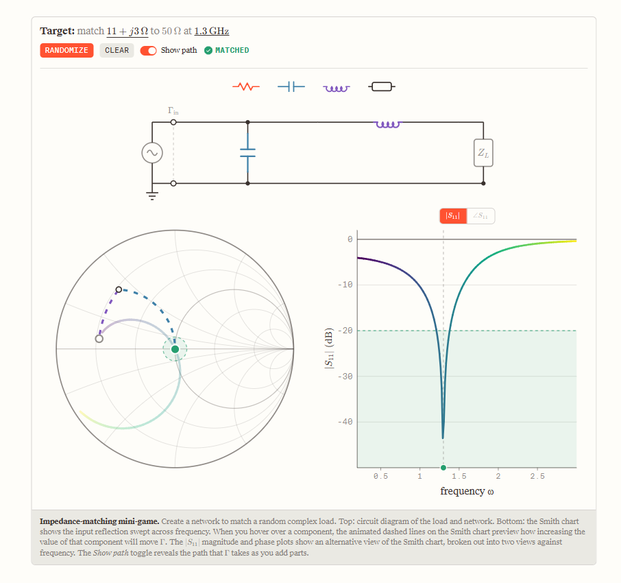
As a reward for getting through everything, there is a fascinating interactive game. In this game, you are shown a plain circuit and a couple of charts including a Smith Chart. Your goal is to add components to the circuit, in series or parallel, to bring the circuit into a match condition. You can use resistors, capacitors or inductors in series or in parallel, and transmission line stubs in series. Remember resistors convert energy into heat, so they reduce the transmitted energy; avoid using resistors.
Click the "Randomize" button to get another puzzle to solve. [[Editor's note: I found this game to be quite educational and somewhat addicting. ]]
A few observations that might help you.
- When placing a capacitor or inductor in parallel, the "Value circle" will be based on the LEFT side of the chart.
- When placing a capacitor or inductor in series, the "Value circle" will be based on the RIGHT side of the chart.
- The order of capacitors and inductors matters.
- Combining capacitors and inductors with both in series or parallel doesn't help. Try putting one or the other in the other part of the circuit.
- Remember, using resistors is bad. They are colored red in the game for a reason.
Challenges
- Can you find a match for 5 different puzzles using only capacitors and inductors?
- How does changing the feedline length affect your choice of matching components?